 FIXONIC
Official iFixit API visual reference
Open the authorised source
iPhone 16 Rear Camera Assembly Removal
Attributed iFixit repair guide for iPhone 16.
Apple iPhone 16
Moderate
45 minutes - 1 hour
Guide 180990
Licensed iFixit integration
This attributed iFixit guide is displayed through Fixonic's recorded commercial API permission. iFixit remains the independent source and author of the procedure.


Tape over any cracks


Remove the pentalobe screws


Mark your opening picks


Heat the bottom edge


Insert an opening pick

- Apply a suction handle to the bottom edge of the back glass.
- While supporting the frame with one hand, pull up on the handle with a strong, steady force to create a gap between the back glass and the frame.
- Insert the tip of an opening pick into the gap.
Back glass information

- A delicate cable connecting the back glass to the phone, right next to the volume down button. Don't insert your pick here to avoid slicing the cable.
- Multiple spring contacts around the perimeter of the phone.
Heat the right edge

Separate the bottom right adhesive

- Slide your pick around the bottom right corner and to the volume down button to separate the adhesive and release the metal clip.
- Leave this pick inserted to prevent the adhesive from resealing.
Heat the left edge

Separate the left adhesive

- Insert a second opening pick at the bottom edge.
- Slide the second pick around the bottom left corner and along the left edge of the screen to separate the adhesive and release the metal clips.
- Leave this pick inserted at the top left corner to prevent the adhesive from resealing.
Heat the top edge

Separate the top right adhesive

- Slide your second opening pick around the top left corner and along the top edge to separate the adhesive and release the metal clips.
- Continue sliding your pick around the top right corner until you reach the Action button.
- Leave this pick inserted to prevent the adhesive from resealing.
Reposition the back glass

- Swing open the back glass to the right of the phone to separate the remaining adhesive.
- Support the back glass with a clean, sturdy object.
- Remove the opening picks before continuing.
Remove the middle connector cover screws

Remove the middle connector cover

- Insert the point of a spudger in either cutout on the middle connector cover.
- Slide the cover towards the left edge of the phone and release its hook from its slot on the logic board.
- Remove the cover.
Disconnect the battery

Disconnect the wireless charging coil

Remove the back glass
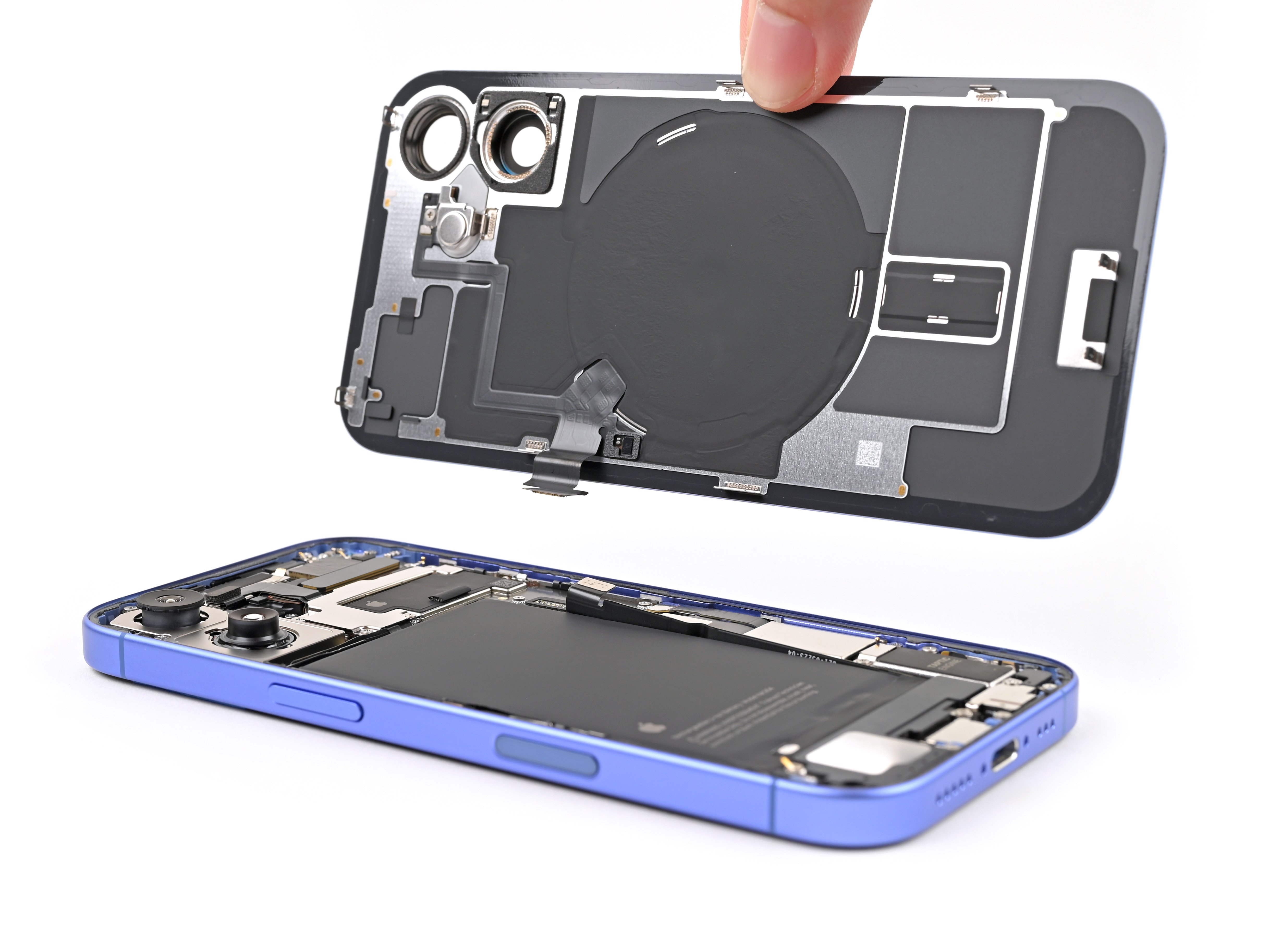
- Lift the back glass off the frame and remove it.
Remove the top bracket screws


- Use a screwdriver to remove the four screws securing the top bracket:
- One 3.5 mm-long Phillips screw
- Two 1.4 mm-long Phillips screws
- One 1.0 mm-long tri-point Y000 screw
Remove the top bracket

Disconnect the rear camera assembly

Remove the rear camera assembly screws

- Use a Phillips screwdriver to remove the three screws securing the rear camera assembly:
- One 2.3 mm‑long screw
- One 4.7 mm‑long screw
- One 3.2 mm‑long screw
Remove the rear camera assembly

- Insert the tip of a spudger into the top screw hole in the rear camera assembly.
- Lift the rear camera assembly out of the frame and remove it.