 FIXONIC
Official iFixit API visual reference
Open the authorised source
(New) iPhone 15 Logic Board Removal
Attributed iFixit repair guide for iPhone 15.
Apple iPhone 15
Moderate
1 - 4 hours
Guide 191703
Licensed iFixit integration
This attributed iFixit guide is displayed through Fixonic's recorded commercial API permission. iFixit remains the independent source and author of the procedure.


Tape over any cracks


Mark your opening picks


Remove the pentalobe screws


Screen information

- For easier screen removal in the next steps, note the following:
- There's a plastic bezel on the underside of the screen. Your opening pick will go underneath this bezel.
- There's a seam between the plastic bezel and the display panel. Don't insert your pick here or you'll separate the two.
Heat the bottom edge


Insert an opening pick

- Apply a suction handle to the bottom edge of the screen.
- Pull up on the handle with a strong, steady force to create a gap between the screen and the frame.
- Insert the tip of an opening pick into the gap.
Screen information

- There are two delicate cables connecting the screen to the phone, one just above the mute switch, and the other about halfway between the volume down button and the bottom of the phone.
- There are multiple spring contacts around the perimeter of the phone. Be extra careful not to insert your pick deeper than suggested in these locations to avoid bending the contacts.
Separate the bottom edge adhesive

- Slide your pick back and forth along the bottom edge to separate the adhesive.
- Leave your pick inserted in the bottom right corner to prevent the adhesive from re-sealing.
Heat the right edge

- Heat the right edge of the screen until it's hot to the touch.
Position the opening pick

- Slide your pick around the bottom right corner of the screen and toward the power button until you feel a hard stop at a clip securing the screen.
- Rotate your pick so the flat edge is under the screen.
Release the right clip

- Hold the pick with one hand and twist it to increase the gap between the screen and the frame and release the right clip.
- Insert a second opening pick to the right of the first one.
Separate the right edge adhesive

- Slide the first pick back to the bottom right corner of the screen.
- Slide the second pick to the top right corner of the screen to separate the adhesive.
- Leave these picks inserted to prevent the adhesive from resealing.
Heat the top edge

- Heat the top edge of the screen until it's hot to the touch.
Separate the top right corner adhesive

- Insert a third opening pick in the top right corner, just above the previous pick.
- Slide your pick around the top right corner and along the top edge until you feel it stop against the top left screen clip.
Release the top edge clips

- Rotate your pick so its flat edge is under the screen.
- Twist your pick to release the top left screen clip.
- Slide your pick to the top left corner.
Heat the left edge

- Heat the left edge of the screen until it's hot to the touch.
Separate the left edge adhesive

Swing open the screen

Unfasten the front sensor connector cover

Remove the cover

Disconnect the front sensor

Unfasten the screen connector cover

Remove the cover

Disconnect the screen
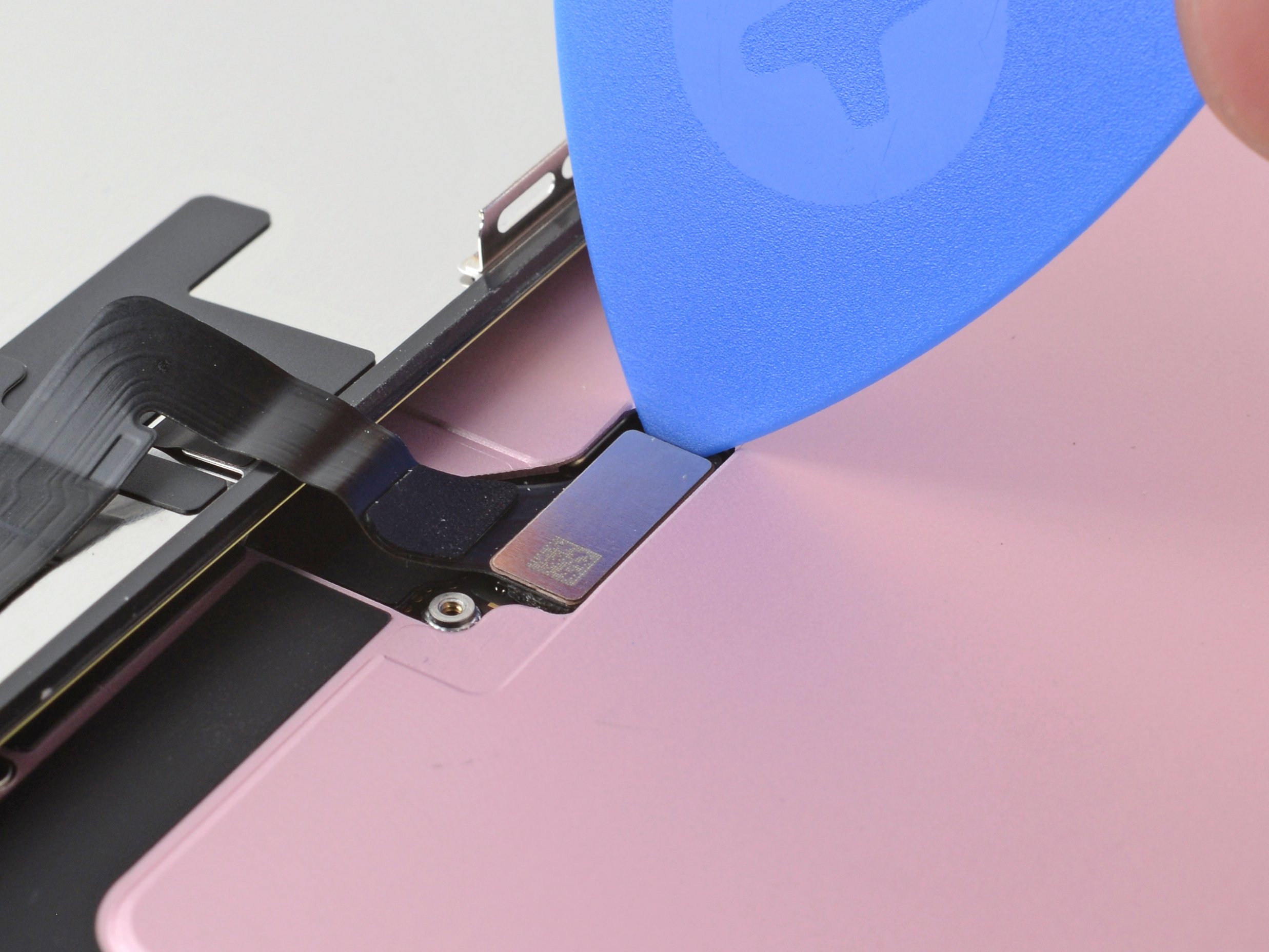
Remove the screen

- Remove the screen.
Heat the bottom edge

Insert an opening pick

- Apply a suction handle to the bottom edge of the back glass.
- Pull up on the handle with a strong, steady force to create a gap between the back glass and the frame.
- Insert the tip of an opening pick into the gap.
Back glass information

- There's a delicate cable connecting the back glass to the phone, right next to the volume down button. Don't insert your pick here to avoid slicing the cable.
- There are multiple spring contacts around the perimeter of the phone. Be extra careful not to insert your pick deeper than suggested in each step to avoid bending these contacts.
Separate the bottom edge adhesive

- Slide your pick back and forth along the bottom edge to separate the adhesive.
- Leave your pick inserted in the bottom right corner to prevent the adhesive from re-sealing.
Heat the right edge

- Heat the right edge of the back glass until it's hot to the touch.
Separate the bottom right corner adhesive

- Rotate your pick around the bottom right corner and slide it to the volume down button or until you feel a hard stop at a large clip securing the back glass.
- Leave this pick inserted to prevent the adhesive from resealing.
Heat the left edge

- Heat the left edge of the back glass until it's hot to the touch.
Separate the left edge adhesive

- Insert a second opening pick at the bottom edge.
- Rotate the second pick around the bottom left corner.
- Slide this pick up to the top left corner to separate the adhesive.
- Leave this pick inserted to prevent the adhesive from resealing.
Heat the top edge

- Heat the top edge of the back glass until it's hot to the touch.
Separate the top edge adhesive

- Rotate your second opening pick around the top left corner and slide it to the top right corner to separate the adhesive.
- Leave this pick in place to prevent the adhesive from resealing.
Heat the top right corner

- Heat the top right corner of the back glass until it's hot to the touch.
Separate the top right corner adhesive

Open the back glass

Unfasten the lower connector cover

Remove the lower connector cover

Disconnect the battery
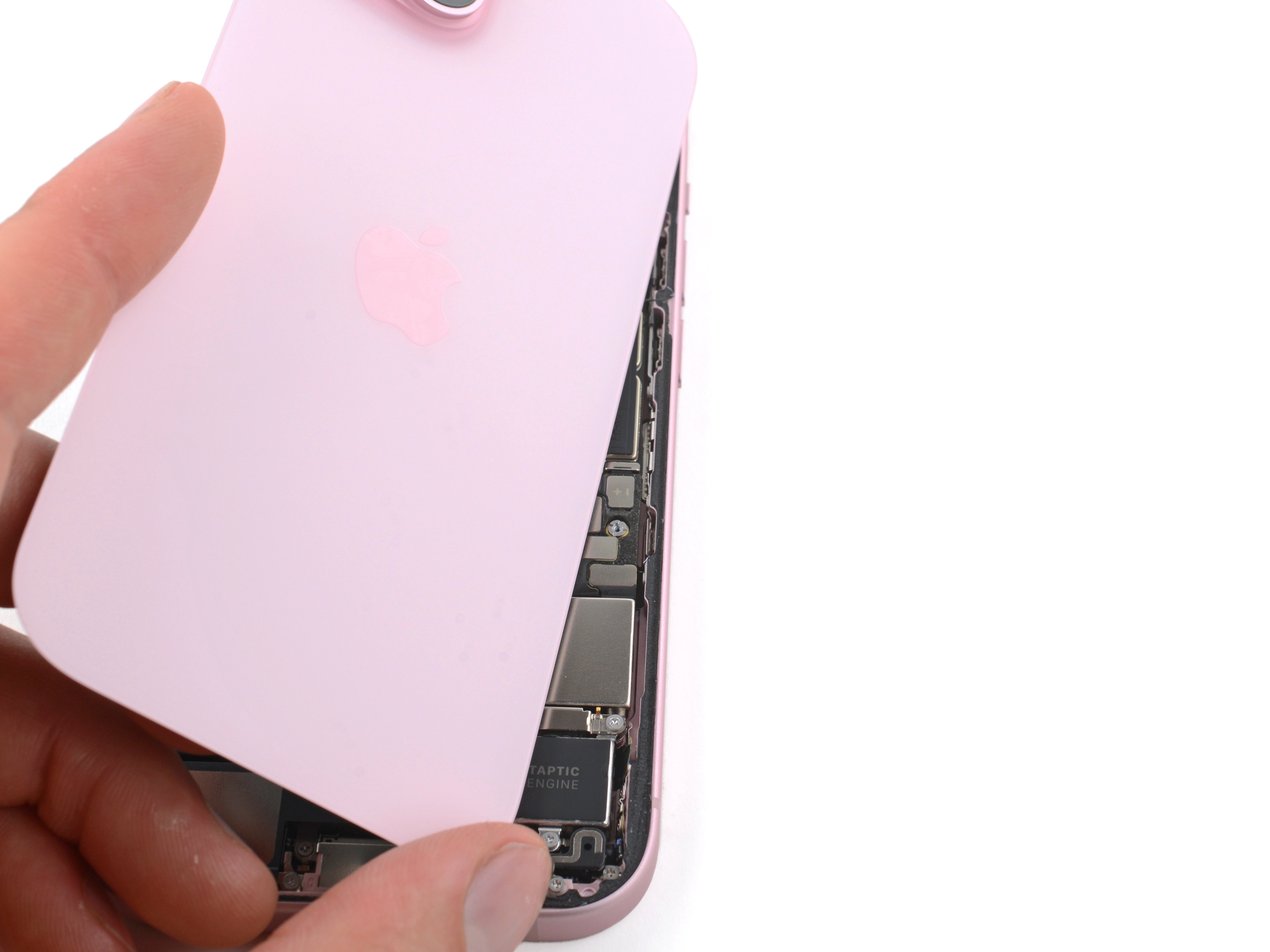
- Hold the back glass upright with one hand and rotate it just enough to reveal the battery press connector just below the volume buttons.
- Use the tip of an opening pick to pry up and disconnect the battery press connector from the logic board.
Unfasten the middle connector cover

Remove the cover

- Use the flat end of a spudger or your finger to push the cover toward the bottom of the phone and unclip its top edge.
- Remove the cover.
Disconnect the wireless charging coil

Remove the back glass

- Remove the back glass.
Remove the upper connector cover

- Use your tri-point Y000 driver to remove the two 1.3 mm‑long screws securing the upper connector cover.
- Remove the cover.
Disconnect the front camera and sensors

- Use the tip of an opening pick to pry up and disconnect the antenna, front sensors, and front camera press connectors (three connectors in total).
Remove the front camera and sensors

Disconnect the earpiece speaker

Unfasten the earpiece speaker

- Use a Phillips #000 driver to remove the five screws securing the earpiece speaker:
- Two 1.1 mm‑long screws
- Three 1.6 mm‑long screws
Remove the earpiece speaker

Separate the battery cable

Disconnect the volume buttons

Disconnect the power button

Disconnect the rear cameras and antenna

Disconnect the eSIM, Taptic Engine, and charging port

Unfasten the logic board

- Use your standoff driver to remove the five standoff screws securing the logic board:
- One 2.9 mm‑long screw
- One 3.9 mm‑long screw
- Three 3.5 mm‑long screws
